Appearance
Filter Nodes
Filter nodes route points into Inside / Out (or Out) outputs based on spatial, numeric, or set-theoretic criteria. They never modify point data — only which output the point flows into.
All filter nodes are in the Filters category and share the dark-red node color.
Difference
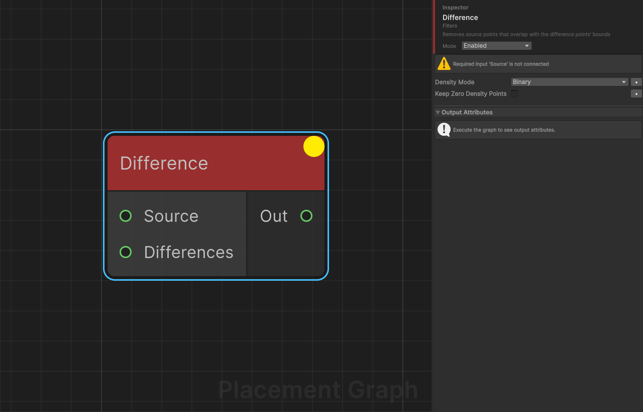
Description: Removes source points that overlap with the difference points' bounds. The spatial inverse of Intersection.
Ports
| Name | Direction | Type | Notes |
|---|---|---|---|
| Source | Input | Point | Required. Points to subtract from. |
| Differences | Input | Point | Required. One or more point sets that define the subtracted region. Accepts multiple connections. |
| Out | Output | Point | Surviving source points. |
Settings
| Field | Type | Default | Description |
|---|---|---|---|
densityMode | PPGDensityFunction | Binary | How density is recalculated after subtraction. Binary: a point is removed if any overlap exists, otherwise density is unchanged. Minimum: density is multiplied by (1 - maxOverlapRatio), allowing partial overlap to reduce rather than eliminate a point. |
keepZeroDensityPoints | bool | false | When enabled, points that reach zero density (instead of being removed) are kept in the output with density = 0. Useful for downstream masking. |
Notes
- Overlap is tested in world space using each point's AABB (
boundsMin/boundsMax). Make sure bounds are set correctly before this node (see Bounds Modifier). - When Differences is disconnected or empty, all source points pass through unchanged.
- Minimum mode is useful for soft feathering at the boundary; Binary is a clean hard cut.
Filter by Attribute
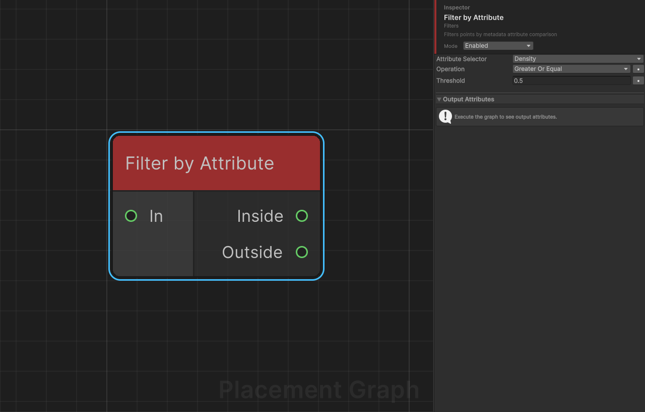
Description: Filters points by comparing a named float metadata attribute against a numeric threshold. Points that pass the comparison go to Inside; the rest go to Outside.
Ports
| Name | Direction | Type | Notes |
|---|---|---|---|
| In | Input | Point | Points to filter. |
| Inside | Output | Point | Points that pass the comparison. |
| Outside | Output | Point | Points that fail the comparison. |
Settings
| Field | Type | Default | Description |
|---|---|---|---|
attributeSelector | PPGAttributeSelector | (none) | The metadata attribute (or built-in point property) to read and compare. Must resolve to a float value. |
operation | CompareOp | GreaterOrEqual | Comparison operator: Equal, NotEqual, Greater, GreaterOrEqual, Less, LessOrEqual. Equality uses an epsilon of 1e-6. |
threshold | float | 0.5 | The value the attribute is compared against. |
Notes
- If
attributeSelectoris not set (invalid), every point is routed to Outside. - Use this node together with Distance or Nearest Seed Assign to filter by computed attributes.
- You can leave Outside unconnected if you only need the passing set.
Filter by Bounds
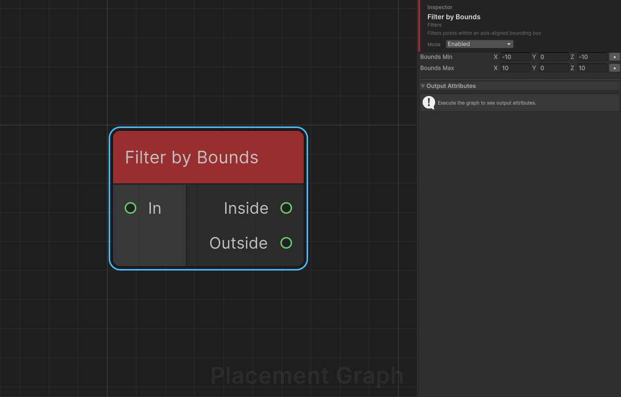
Description: Filters points within an axis-aligned bounding box (AABB) defined in local space. Points whose position lies inside the box go to Inside; the rest go to Outside.
Ports
| Name | Direction | Type | Notes |
|---|---|---|---|
| In | Input | Point | Points to filter. |
| Inside | Output | Point | Points within the bounding box. |
| Outside | Output | Point | Points outside the bounding box. |
Settings
| Field | Type | Default | Description |
|---|---|---|---|
boundsMin | Vector3 | (-10, 0, -10) | Minimum corner of the filter box in local space. |
boundsMax | Vector3 | (10, 0, 10) | Maximum corner of the filter box in local space. |
Notes
- When
boundsMin.y == boundsMax.y(the default, both0), the Y axis check is skipped — the filter becomes a 2D XZ-plane rectangle test. Set them to different values to enable Y-axis clamping. - This node uses a Burst-compiled parallel job, making it efficient for large point sets.
- All positions are in the component's local space (before the component's own Transform is applied).
Filter by Density
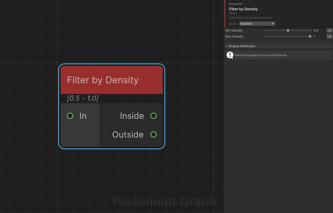
Description: Filters points whose density value falls within a [minDensity, maxDensity] range. Points in range go to Inside; others go to Outside.
Ports
| Name | Direction | Type | Notes |
|---|---|---|---|
| In | Input | Point | Points to filter. |
| Inside | Output | Point | Points within the density range. |
| Outside | Output | Point | Points outside the density range. |
Settings
| Field | Type | Default | Description |
|---|---|---|---|
minDensity | float [0..1] | 0.5 | Minimum density (inclusive) for a point to pass. |
maxDensity | float [0..1] | 1.0 | Maximum density (inclusive) for a point to pass. |
Notes
- Density is a normalized
[0, 1]per-point float that represents relative importance or probability of placement. - This node uses a Burst-compiled parallel job.
- A common pattern is to use Distance to write density, then this node to select a band by proximity.
Filter by Index
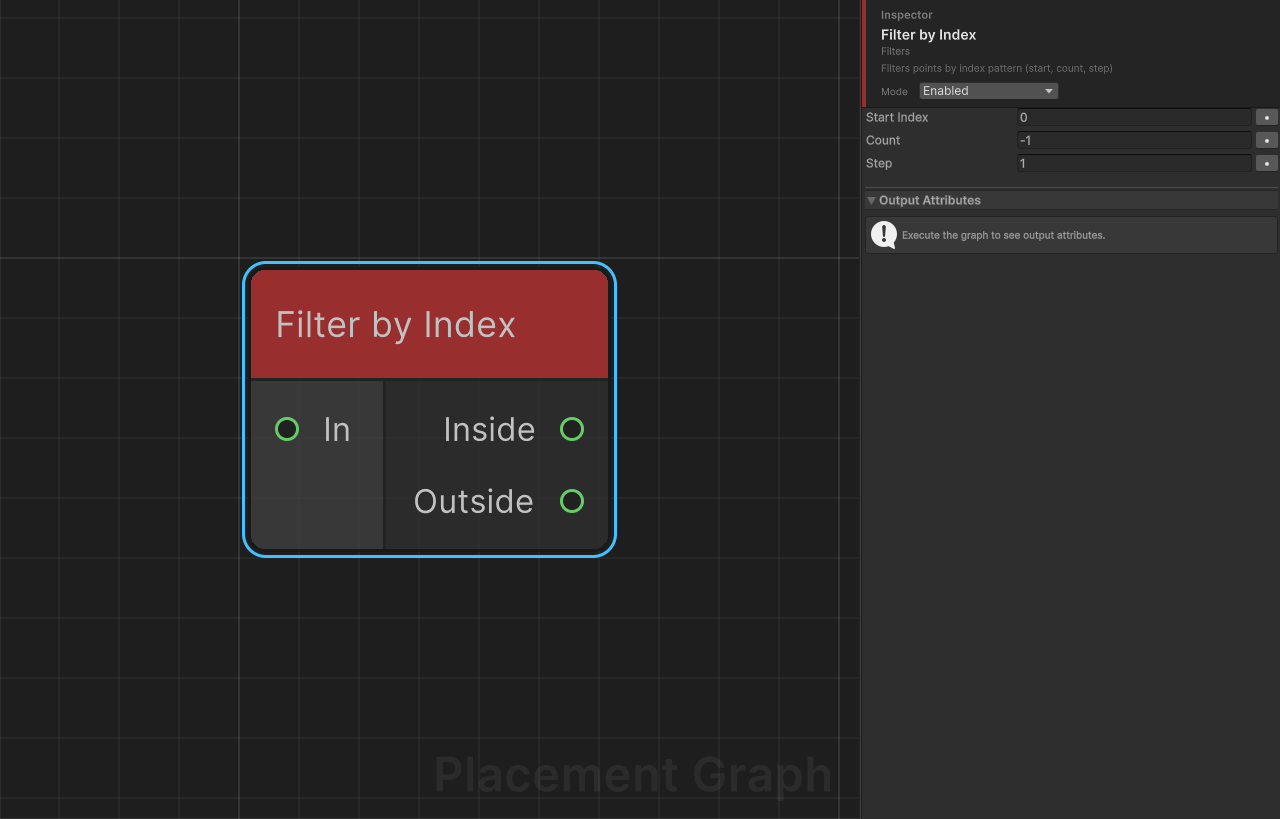
Description: Routes points to Inside or Outside based on their sequential index in the input stream. Supports configurable start offset, count limit, and step (every Nth point).
Ports
| Name | Direction | Type | Notes |
|---|---|---|---|
| In | Input | Point | Points to filter. |
| Inside | Output | Point | Points matching the index pattern. |
| Outside | Output | Point | Points not matching the pattern. |
Settings
| Field | Type | Default | Description |
|---|---|---|---|
startIndex | int | 0 | First global index to include. Negative values are clamped to 0. |
count | int | -1 | Number of points to include. -1 means "all remaining from start". |
step | int | 1 | Include every Nth point from the start. 1 = every point, 2 = every other point, etc. Values below 1 are clamped to 1. |
Notes
- The index counter is global across all connected inputs, not per-input. If multiple point sets are connected, they are indexed continuously.
- Example:
startIndex=0, count=10, step=2keeps indices 0, 2, 4, 6, 8. - Useful for selecting alternating rows, every Nth tree, or a specific head/tail slice of a set.
Filter by Normal

Description: Filters points by comparing the point's up-vector (Y column of its transform) against a reference direction. Points within maxAngle degrees of the reference are sent to Inside; others to Outside.
Ports
| Name | Direction | Type | Notes |
|---|---|---|---|
| In | Input | Point | Points to filter. |
| Inside | Output | Point | Points whose normal is within the angle limit. |
| Outside | Output | Point | Points whose normal exceeds the angle limit. |
Settings
| Field | Type | Default | Description |
|---|---|---|---|
referenceDirection | Vector3 | (0, 1, 0) | The direction to compare normals against. Automatically normalized at runtime. |
maxAngle | float | 30 | Maximum allowed angle in degrees between the point's up-vector and the reference direction. |
Notes
- The angle comparison is done using a dot-product threshold (
cos(maxAngle)) instead ofacos, which is more efficient. - After Project to Surface, the point's up-vector stores the surface normal — use this node to separate flat and steep areas.
- This node uses a Burst-compiled parallel job.
Filter by Spline
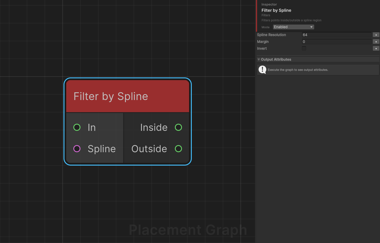
Description: Filters points based on whether they fall inside or outside a spline region on the XZ plane. For closed splines, uses a ray-casting point-in-polygon test. For open splines, uses a distance-to-curve test.
Ports
| Name | Direction | Type | Notes |
|---|---|---|---|
| In | Input | Point | Points to filter. |
| Spline | Input | Spline | The spline that defines the filter region. |
| Inside | Output | Point | Points inside the spline region. |
| Outside | Output | Point | Points outside the spline region. |
Settings
| Field | Type | Default | Description |
|---|---|---|---|
splineResolution | int | 64 | Number of samples used to approximate the spline as a polygon. Minimum clamped to 8 at runtime. Higher values improve accuracy at curved boundaries. |
margin | float | 0.0 | Boundary margin in world units. Positive: expands the inside region (points near the outside of the boundary are included). Negative: shrinks the inside region (points near the inside of the boundary are excluded). For open splines, acts as the inclusion radius. |
invert | bool | false | If true, the Inside and Outside results are swapped. |
Notes
- The spline is sampled in world space and converted to the component's local XZ plane for testing. The Y axis is ignored.
- If the Spline input is disconnected or has fewer than 2 knots, a warning is logged and all points pass through to Inside.
- For open splines, a minimum effective radius of
0.5is applied even whenmarginis0. - Uses
UnityEngine.Splines(Splines package). The spline must be connected via a Spline data node.
Intersection
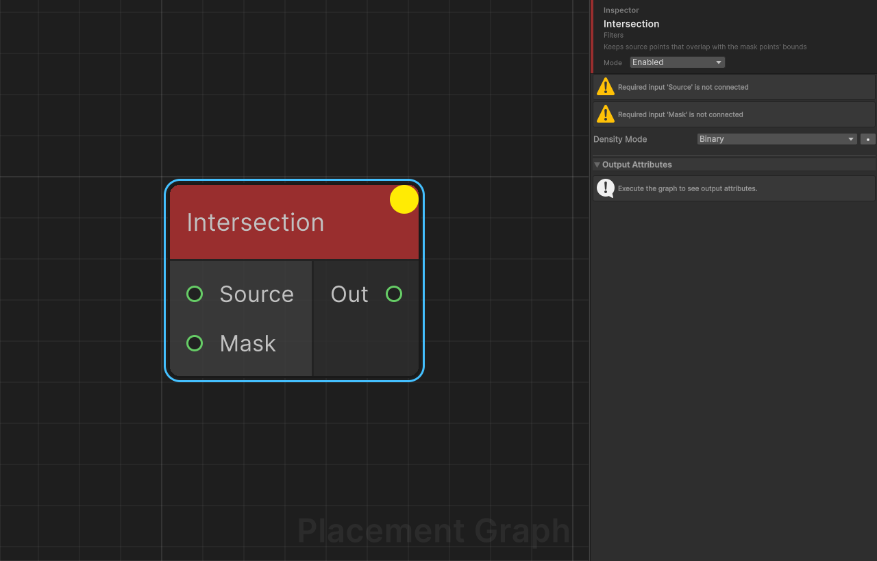
Description: Keeps only source points that spatially overlap with the mask points' bounds. The spatial complement of Difference.
Ports
| Name | Direction | Type | Notes |
|---|---|---|---|
| Source | Input | Point | Required. The point set to test. |
| Mask | Input | Point | Required. One or more point sets that define the keep region. Accepts multiple connections. |
| Out | Output | Point | Source points that overlap with the mask. |
Settings
| Field | Type | Default | Description |
|---|---|---|---|
densityMode | PPGDensityFunction | Binary | How density is computed for kept points. Binary: density is unchanged for any point with overlap. Minimum: density is multiplied by the maximum overlap ratio, attenuating points that only partially overlap. |
Notes
- If Mask is disconnected or empty, no points are output (the mask acts as a gate).
- Overlap is tested via world-space AABB intersection, so ensure bounds are set appropriately beforehand.
- Contrast with Difference: Difference removes overlapping points; Intersection keeps only overlapping points.
Union
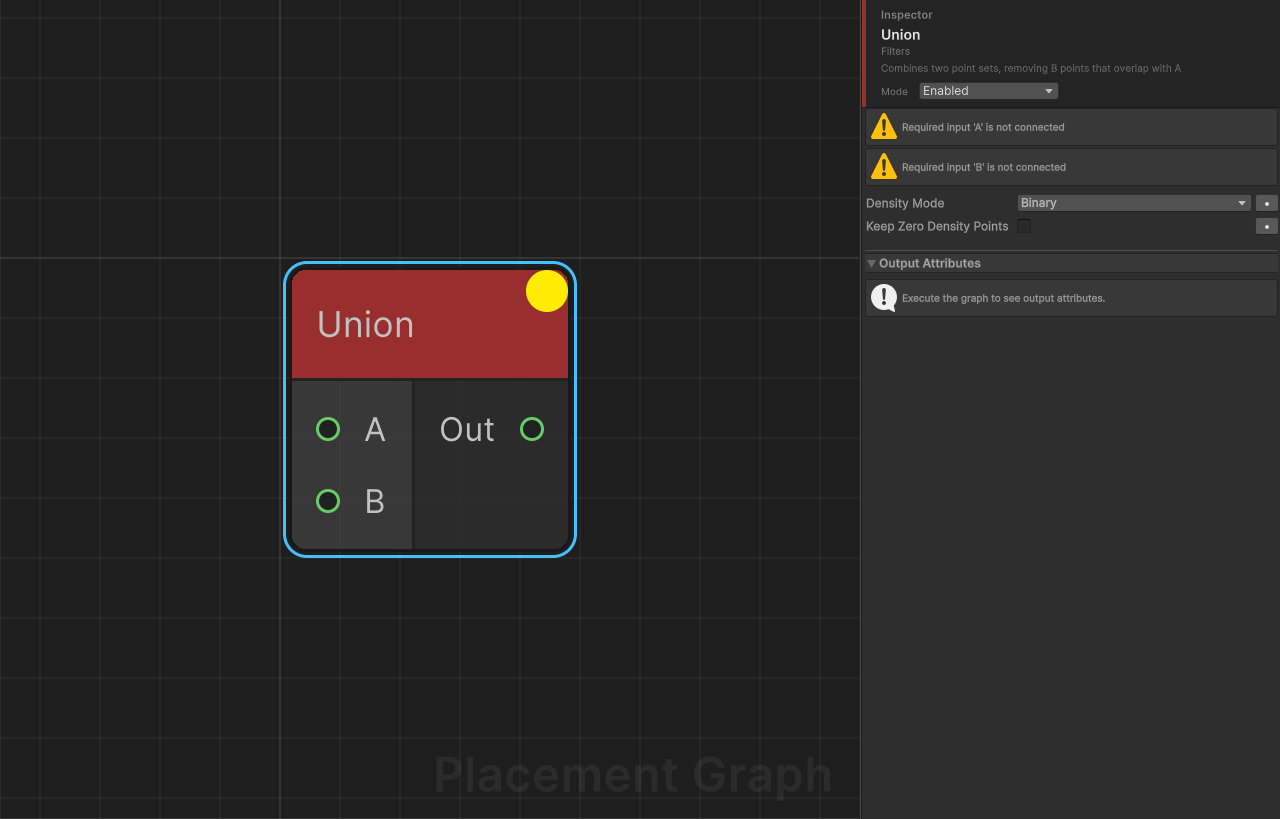
Description: Combines two point sets into one, preventing spatial duplicates. All points from A are kept. Points from B that do not overlap any point in A are also added.
Ports
| Name | Direction | Type | Notes |
|---|---|---|---|
| A | Input | Point | Required. Primary point set; all points are always kept. |
| B | Input | Point | Required. Secondary point set; only non-overlapping points are added. |
| Out | Output | Point | Combined point set without spatial duplicates. |
Settings
| Field | Type | Default | Description |
|---|---|---|---|
densityMode | PPGDensityFunction | Binary | How density is handled for B points near A. Binary: B points that overlap A are dropped entirely. Minimum: B point density is multiplied by (1 - maxOverlapRatio); both may survive with reduced density. |
keepZeroDensityPoints | bool | false | When using Minimum mode, keeps B points that reach density = 0 instead of removing them. Only relevant in Minimum mode. |
Notes
- If A is empty, all B points pass through unchanged (and vice versa).
- Output metadata is cloned from the first A input.
- This is a spatial union, not a simple concatenation — use Merge if you want to combine all points without overlap testing.
- B points that overlap multiple A points are judged against the single A point with the highest overlap ratio.